4 Types of Grounding Systems in Electrical Installations
Basically, we should have four types of grounding systems in our industrial electrical installations
Grounding is very Importent, ensuring smooth operation of our control systems and to minimize upon electrical shock hazards, noise, static electricity, etc.
Therefore, we always should create two separate paths to ground for our Protection Earth (PE) and our Instrumentation Earth (IE).
Basically, we should have four types of grounding systems in our industrial electrical installations :
When having multiple bulidings, using one combined MCC or buildings that are within 5 meters of each other, then the grounding systems of corresponding buildings should be bonded / connected with each other to prevent potential differences among our equipment / instruments , etc.
1. Functional Earth (FE)
4 Types of Grounding Systems
Grounding PrinciplesGrounding is very Importent, ensuring smooth operation of our control systems and to minimize upon electrical shock hazards, noise, static electricity, etc.
Therefore, we always should create two separate paths to ground for our Protection Earth (PE) and our Instrumentation Earth (IE).
Basically, we should have four types of grounding systems in our industrial electrical installations :
- Functional Earth (FE) Grounding
- Protective Earth (PE) Grounding
- Instrumentation Earth (IE) Grounding
- Lightning Earth (LE) Grounding / Protection
When having multiple bulidings, using one combined MCC or buildings that are within 5 meters of each other, then the grounding systems of corresponding buildings should be bonded / connected with each other to prevent potential differences among our equipment / instruments , etc.
Grounding Pits
Grounding pits should be able to be drained out properly, they should be kept clean, easy accessible, well marked / labelled and inspected regularly to prevent on corrosion, etc. That could jeopardize the groundings integrity.
 |
| Types of Grounding |
1. Functional Earth (FE)
Functional Earth Grounding is used to establish a good and stable potential point for our neutral (N) and DC Commons (0 vdc).
Functional Earth Grounding is one of the most important connections in our Plants and therefore we must make sure that they are Properly attached to corresponding grounding system; we will have floating neutral or DC commons, in case we do not, jeopardizing the entire plant performance, like equipment malfunctioning/ startup problems, instrument miss-reading, etc
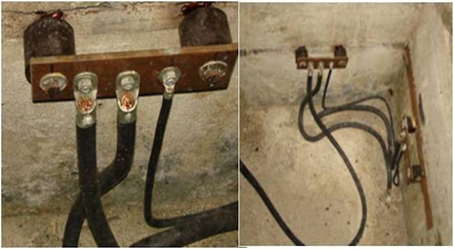
The grounding bar of each transformer should be connected directly with corresponding transformer ground and neutral bar and not via another intermediate such as a metal bean on where corresponding transformer is mounted or a metal terminal strip.
The Grounding bar should be galvanized (e.g zinc and steel or zinc and cupper) to prevent it from rusting / corroding , having a proper grounding for the short and long run. Rusted / corroded steel or cupper will result in an isolated connection jeopardizing the overall performance, in case it is used as grounding. Therefore every grounding connection should be galvanized and properly connected, quaranteeing corresponding grounding for the long-run.
The DC Common of our DC Power Supplies should be tied up with instrumentation Earth (IE) Grounding
2. Protective Earth (PE)
Protection Earth (PE)
The mean reason for safety Protection Earth (PE) grounding is to create a path to ground.
In case there is a fault, breaking /opening corresponding circuit breaker, preventing electrical shock hazards.
Motor safety (PE) grounding
There are three methods to accomplish a good motor grounding, hereby option 3 is prefered :
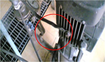
1. Run a ground wire from our MCC to corresponding motor (PE).
2. Connect the motor, as all our equipment, to grounding grid by means of installing it straight on our buliding steel construction or via a grounding bar (Zinc steel or zinc copper) that is MIG (thermal) welded on one of buliding steel columns.
Note : we have to make sure that all the buliding steel is bonded together to the grounding grid.
3. Combination of 1 and 2 to ensure that there is a path to ground at anytimes / circumtances.
Note : we do not have to worry about ground – loops for our motor grounding, it also will not jeopardize the overall performance of the grounding grid / system as all our equipment (building steel, piping, tanks, motor, etc.) are bonded together to the same grounding grid.
A cupper band that is connected with a cable – conduit or cable tray is not a proper connection and could jeopardize the grounding of corresponding equipment.
Process piping cannot be used / assigned as the PE grounding of our motor either, process piping, flences, etc cannot guarantee a proper path to ground. Therefore, we always should perform above mentioned and hereby a combination of method 1 and 2 is preferred.
Transformer safety (PE) grounding
Every piece of metal inside transformer room / area must be grounded properly.
Each piece of metal that is not grounded properly can work as antena, introducing EMI (Electronic Magnetic Interference) and other kind of problems in our other systems.
Furthermore, we can have transformer effect between exposed high voltage parts and metal parts near by.
This cause anything from a bulid up of static charge, to an actual shock hazard bad enough injury or even death.
Notes :
Metal parts of the transformer itself that is bolted together should have grounding strips.
The oil temperature and oil level switches of a transformer cooling unit must be checked during comissioning, but also once a year during normal operation. We have to make sure that bolt swithces will shut – down the transformer in case of calamities.
Using multiple grounding points / rods is good, but they should be connected with each other, bonded to one general grounding system, to ensure that every floats equally, in case of major fault.
Miscellaneously safety (PE) grounding:
Every piece oe electrical equipment should have its PE wire / bar connected to prevent electrical shock hazards. At any circumtances, we should not allow leaving PE wiring are unconnected.
All other equipment, such as cable trays, tanks, piping, etc should be properly attached to our buliding steel / grounding system as well to have our equipment bonded together (at an equal potential).
When having multiple bulidings, using one combined MCC or bulidings that are within 5 meters of each others, then the grounding systems of corresponding buildings should be bonded / connected with each other to prevent potential differences among our equipment / instruments etc.
Lightning strikes can give rise of harmful potential differences in and on a building.
The major concern in the protection of a building is the occurrence of potential differences between the conductor of the lightningprotection system and other grounded metal bodies and wires belonging to the building.
These potential differences are caused by resistive and inductive effects and can be of such a magnitude that dangerous sparking can occur. In order to reduce the possibility of sparking, itis neccessary to equalize potential by bonding grounded metal bodies, building etc to our building grounding systems.
Tank – farm grounding
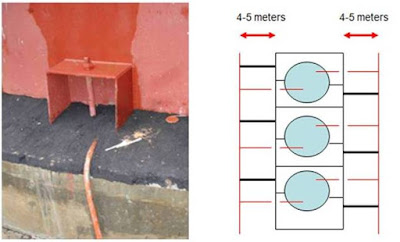
Normally, we should create a grid around all our tanks, having each tank connected to this grid by at least 2 points.
General grounding notes :
Good practices is having all grounding system attached to each other , in example attaching the MCC / DCS building, plant grounding system with all other grounding systems, including the tank – farm grounding system, this approach will quarantee that we do have the same potential at all our grounding systems to which major faults ets could flow to.
We should make sure or verify (on regular bases) that each grounding system is done properly, < 5 ohm for safety / lightning grounding and < 1 ohm for instrumentation grounding.
Pipe bonding and grounding Below mentioned applies, when it is neccessary to properly bond and ground our piping, e.g. when used within / for explosive hazardous areas / mediums :
1. Bonding All pipes, flanges, tanks, etc. To be electrically bonded / connected at < 10 ohms - Use >= 6 mm2 bonding – cable / strip across all flanges – it should be a bare cupper cable / strip (without insulation) to prevent damaging /melting – off the insulation (cupper would transfer the heat from corresponding piping).
Make sure that proper grounding is achieved at several places , not rely on one grounding point only.
3. Instrument Earth (IE)
A separate grounding rod should be used as instrument ground (IG). This grounding rod should be installed 4 to 5 meters away from the building nearest ground grid (GG) point.
The instrument grounding (IG) should have two connections:
1. To the overall grounding grid / system (it is very important in the event of a major fault that everything floats together, by having this rod linked to the ground grid we will accomplish this goal, at the same time noise in the ground grid will be significantly dissipated before it can have an effect on our instrument and computers).
2. Straight to our PLC / DCS control system panel (creating a separate gronding path for our instruments.
Note :
The grounding grid (GG) and instrument ground (IG) impedance should be both smaller than 5 0hms.
All the affords for having a nice instrument earth (IE) ground could be wasted when corresponding shields are not properly insulated by hot-shrink insulation sleeves for example, as when a bare shield touches the panel, then it would be tied-up to PE instead.
When all done, then we should verify that PE and IE are indeed isolated from each other till the point where it suppose to be tied-up with each other.
4. Lightning Earth (LE)
A Lightning hit into one of our buildings or equipment could damage equipment and interfere its performance, due to high voltage surges during a very short period of time (uSecs).
We have to think about a big ball of 150 foot (46 meters) in diameter when hit by lightning. The lightning protection must be set up in such a way that this ball cannot touch the building surface /roof/ construction without first touching a lightning grounding device.
The lightning consist of:
1. An antena to extract the lightning hit.
2. A grounding cable, which is isolated from corresponding object that needed to be protected against lightning hits, pulled all the way to the ground or lowest point to ground of corresponding object.
We should have at least two connections from the lightning arrestor towards ground, then we are still fine when loosing one.
The lightning grounding cable should not run through a metal counduit, otherwise it will work as a choke (quick rising / falling currents ran through a coil) when actually hit by lightning.
This will increase the voltage level of corresponding lightning hit due to the increased resistance of redirecting the lightning hit to ground caused by the choking affect (~ E (constant) = U²/R), this could result in a damaged lightning grounded cable.
Two options preventing the choking affect:
1. Use plastic conduit, something like drainage pipe will do already (“bumping before breaking”).
2. Properly isolated the metal conduits from the tank, using isolation discs, and connect the lightning grounding cable to the metal conduit at the beginning, end and somewhere in the middle of the metal conduit.
Static electricity
Static Electricity is generated as liquid flows through pipes, valves, and filters during transfer operations.
Proper bonding and grounding ensures that static electricity does not accumulate and spark. Static sparks can readily ignite the vapor – air mixtures of many flammabe and combustible liquids.
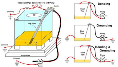
Bonding is the process of electrically connecting, by wiring or direct contact, conductive objects (e.g. fill nozzles to steel tanks) to equalize their individual electrical potential to prevent sparking.
Grounding is connecting a conductive object (e.g. tanks,totes) to the earth to dissipate electricity from accumulate static, lightning strikes, end equipment faults into ground, away from employees and equipment.
Source of static electricity
1. Flow of the following:
3. Interaction with personnel
4. Filtration
5. Settling
6. Bubble rising
Static electricity ignition source
For a static electricity discharge to be a source of ignition, the following four conditions must exist simultaneously :
Protection Earth (PE)
The mean reason for safety Protection Earth (PE) grounding is to create a path to ground.
In case there is a fault, breaking /opening corresponding circuit breaker, preventing electrical shock hazards.
Motor safety (PE) grounding
 |
| Types of Grounding |
1. Run a ground wire from our MCC to corresponding motor (PE).
2. Connect the motor, as all our equipment, to grounding grid by means of installing it straight on our buliding steel construction or via a grounding bar (Zinc steel or zinc copper) that is MIG (thermal) welded on one of buliding steel columns.
Note : we have to make sure that all the buliding steel is bonded together to the grounding grid.
3. Combination of 1 and 2 to ensure that there is a path to ground at anytimes / circumtances.
Note : we do not have to worry about ground – loops for our motor grounding, it also will not jeopardize the overall performance of the grounding grid / system as all our equipment (building steel, piping, tanks, motor, etc.) are bonded together to the same grounding grid.
A cupper band that is connected with a cable – conduit or cable tray is not a proper connection and could jeopardize the grounding of corresponding equipment.
Process piping cannot be used / assigned as the PE grounding of our motor either, process piping, flences, etc cannot guarantee a proper path to ground. Therefore, we always should perform above mentioned and hereby a combination of method 1 and 2 is preferred.
Transformer safety (PE) grounding
 |
| Types of Grounding |
Every piece of metal inside transformer room / area must be grounded properly.
Each piece of metal that is not grounded properly can work as antena, introducing EMI (Electronic Magnetic Interference) and other kind of problems in our other systems.
Furthermore, we can have transformer effect between exposed high voltage parts and metal parts near by.
This cause anything from a bulid up of static charge, to an actual shock hazard bad enough injury or even death.
Notes :
Metal parts of the transformer itself that is bolted together should have grounding strips.
The oil temperature and oil level switches of a transformer cooling unit must be checked during comissioning, but also once a year during normal operation. We have to make sure that bolt swithces will shut – down the transformer in case of calamities.
Using multiple grounding points / rods is good, but they should be connected with each other, bonded to one general grounding system, to ensure that every floats equally, in case of major fault.
Miscellaneously safety (PE) grounding:
Every piece oe electrical equipment should have its PE wire / bar connected to prevent electrical shock hazards. At any circumtances, we should not allow leaving PE wiring are unconnected.
All other equipment, such as cable trays, tanks, piping, etc should be properly attached to our buliding steel / grounding system as well to have our equipment bonded together (at an equal potential).
When having multiple bulidings, using one combined MCC or bulidings that are within 5 meters of each others, then the grounding systems of corresponding buildings should be bonded / connected with each other to prevent potential differences among our equipment / instruments etc.
Lightning strikes can give rise of harmful potential differences in and on a building.
The major concern in the protection of a building is the occurrence of potential differences between the conductor of the lightningprotection system and other grounded metal bodies and wires belonging to the building.
These potential differences are caused by resistive and inductive effects and can be of such a magnitude that dangerous sparking can occur. In order to reduce the possibility of sparking, itis neccessary to equalize potential by bonding grounded metal bodies, building etc to our building grounding systems.
- Resistive effect
- Inductive effect
Tank – farm grounding
 |
| Types of Grounding |
General grounding notes :
Good practices is having all grounding system attached to each other , in example attaching the MCC / DCS building, plant grounding system with all other grounding systems, including the tank – farm grounding system, this approach will quarantee that we do have the same potential at all our grounding systems to which major faults ets could flow to.
We should make sure or verify (on regular bases) that each grounding system is done properly, < 5 ohm for safety / lightning grounding and < 1 ohm for instrumentation grounding.
Pipe bonding and grounding Below mentioned applies, when it is neccessary to properly bond and ground our piping, e.g. when used within / for explosive hazardous areas / mediums :
1. Bonding All pipes, flanges, tanks, etc. To be electrically bonded / connected at < 10 ohms - Use >= 6 mm2 bonding – cable / strip across all flanges – it should be a bare cupper cable / strip (without insulation) to prevent damaging /melting – off the insulation (cupper would transfer the heat from corresponding piping).
- Make sure that the cable / strips contact surface is clean of paint, rust, etc.
- Use proper spring, washers, bolt, nut, etc. So they wont corrode / rust because corrode and rust is an insulator.
Make sure that proper grounding is achieved at several places , not rely on one grounding point only.
3. Instrument Earth (IE)
A separate grounding rod should be used as instrument ground (IG). This grounding rod should be installed 4 to 5 meters away from the building nearest ground grid (GG) point.
The instrument grounding (IG) should have two connections:
1. To the overall grounding grid / system (it is very important in the event of a major fault that everything floats together, by having this rod linked to the ground grid we will accomplish this goal, at the same time noise in the ground grid will be significantly dissipated before it can have an effect on our instrument and computers).
2. Straight to our PLC / DCS control system panel (creating a separate gronding path for our instruments.
Note :
The grounding grid (GG) and instrument ground (IG) impedance should be both smaller than 5 0hms.
All the affords for having a nice instrument earth (IE) ground could be wasted when corresponding shields are not properly insulated by hot-shrink insulation sleeves for example, as when a bare shield touches the panel, then it would be tied-up to PE instead.
When all done, then we should verify that PE and IE are indeed isolated from each other till the point where it suppose to be tied-up with each other.
4. Lightning Earth (LE)
A Lightning hit into one of our buildings or equipment could damage equipment and interfere its performance, due to high voltage surges during a very short period of time (uSecs).
We have to think about a big ball of 150 foot (46 meters) in diameter when hit by lightning. The lightning protection must be set up in such a way that this ball cannot touch the building surface /roof/ construction without first touching a lightning grounding device.
The lightning consist of:
1. An antena to extract the lightning hit.
2. A grounding cable, which is isolated from corresponding object that needed to be protected against lightning hits, pulled all the way to the ground or lowest point to ground of corresponding object.
We should have at least two connections from the lightning arrestor towards ground, then we are still fine when loosing one.
The lightning grounding cable should not run through a metal counduit, otherwise it will work as a choke (quick rising / falling currents ran through a coil) when actually hit by lightning.
This will increase the voltage level of corresponding lightning hit due to the increased resistance of redirecting the lightning hit to ground caused by the choking affect (~ E (constant) = U²/R), this could result in a damaged lightning grounded cable.
Two options preventing the choking affect:
1. Use plastic conduit, something like drainage pipe will do already (“bumping before breaking”).
2. Properly isolated the metal conduits from the tank, using isolation discs, and connect the lightning grounding cable to the metal conduit at the beginning, end and somewhere in the middle of the metal conduit.
Static electricity
Static Electricity is generated as liquid flows through pipes, valves, and filters during transfer operations.
Proper bonding and grounding ensures that static electricity does not accumulate and spark. Static sparks can readily ignite the vapor – air mixtures of many flammabe and combustible liquids.
 |
| Types of Grounding |
Grounding is connecting a conductive object (e.g. tanks,totes) to the earth to dissipate electricity from accumulate static, lightning strikes, end equipment faults into ground, away from employees and equipment.
Source of static electricity
1. Flow of the following:
- Liquids
- Gases
- Solids
- Powders
- Steam
3. Interaction with personnel
4. Filtration
5. Settling
6. Bubble rising
Static electricity ignition source
- It should be clearly understood that primary goal in providing static protection is to eliminate the ignition source of the fire triangle.
- The degree of additional protection needed is spesific to each condition encountered. There are no mandatory electrical code requirements to provide such protection, however hazards do exist and must be considered for safety.
- Generally, the type of installation, type of explosive or flammable atmosphere (dust or gases) and the natural enviroment are all contributing factors to the degree or extent of static electricity as an ignition source.
For a static electricity discharge to be a source of ignition, the following four conditions must exist simultaneously :
- An effective means of separating charge must be present.
- A means of accumulating the separated charges and maintaining a difference of electrical potential must be available.
- A discharge of static electricity of adequate energy must occur.
- The discharge must occur in an ignitable mixture (NEPA 77 – 4.3.1)

Posting Komentar untuk "4 Types of Grounding Systems in Electrical Installations"